Файл:Voyager spacecraft structure.png

Матеріал з Вікіпедії — вільної енциклопедії.
Перейти до навігації Перейти до пошуку

Повна роздільність(960 × 830 пікселів, розмір файлу: 82 КБ, MIME-тип: image/png)

Wikimedia Commons logo Відомості про цей файл містяться на Вікісховищі — централізованому сховищі вільних файлів мультимедіа для використання у проектах Фонду Вікімедіа.
Опис
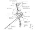
English: The Voyager spacecraft structure - schematic diagram. The 3.7 metre diameter high-gain antenna (HGA) is attached to the hollow ten-sided polygonal electronics bus, with the spherical tank within containing hydrazine propulsion fuel. The Voyager Golden Record is attached to one of the bus sides. The angled square panel to the right is the optical calibration target and excess heat radiator. The three radioisotope thermoelectric generators (RTGs) are mounted end-to-end on the lower boom. The two planetary radio and plasma wave antenna extend diagonally downwards left and right. The 13 metre long Astromast tri-axial boom extends diagonally downwards left and holds the two low-field magnetometers (MAG); the high-field magnetometers remain close to the HGA. The instrument boom extending upwards holds, from bottom to top: the cosmic ray susbsystem (CRS) left, and Low-Energy Charged Particle (LECP) detector right; the Plasma Spectrometer (PLS) right; and the scan platform that rotates about a vertical axis. The scan platform comprises: the Infrared Interferometer Spectrometer (IRIS) (largest camera at top right); the Ultraviolet Spectrometer (UVS) just above the UVS; the two Imaging Science Subsystem (ISS) vidicon cameras to the left of the UVS; and the Photopolarimeter System (PPS) under the ISS. Suggested for English Wikipedia:alternative text for images: A space probe with squat cylindrical body and a large parabolic radio antenna dish pointing left, a three-element radioisotope thermoelectric generator on a boom extending down, and scientific instruments on a boom extending up. A disk is fixed to the body facing front left. A long tri-axial boom extends down left and two radio antenna extend down left and down right.
Polski: Schemat konstrukcji sondy Voyager
Час створення (UTC)
Джерело
Автор


Це відредаговане зображення, тобто одержане цифровою обробкою з оригіналу. Зміни: png version. Початкове зображення знаходиться тут: Voyager spacecraft structure.jpg. Відредагував Andrzej Mirecki.


Public domain Цей файл перебуває у суспільному надбанні, оскільки він був створений NASA (Національним управлінням з аеронавтики і дослідження космічного простору). Згідно з політикою NASA стосовно авторського права, «матеріали NASA не захищаються авторським правом, якщо не вказано протилежне». (Див. Template:PD-USGov, сторінку політики NASA стосовно авторського права, або політику використання зображень JPL.)
Попередження:

Журнал завантажень локального файлу

This image is a derivative work of the following images:

  • File:Voyager_spacecraft_structure.jpg licensed with PD-USGov-NASA
    • 2009-12-04T05:10:09Z Camilo Sanchez 800x1000 (240467 Bytes) Reverted to version as of 19:07, 24 July 2008
    • 2009-12-04T05:07:12Z Camilo Sanchez 744x1052 (1047702 Bytes) Raster to vector version
    • 2008-07-24T19:07:56Z Mirecki 800x1000 (240467 Bytes) {{Information |Description={{en|1=The Voyager spacecraft structure - schematic diagram}} {{pl|1=Schemat konstrukcji sondy Voyager}} |Source=The Voyager Neptune Travel Guide |Author=NASA |Date=June 1, 1989 |Permission= |other_

Uploaded with derivativeFX

Підписи

Додайте однорядкове пояснення, що саме репрезентує цей файл

Об'єкти, показані на цьому файлі

зображує

Історія файлу

Клацніть на дату/час, щоб переглянути, як тоді виглядав файл.

Дата/часМініатюраРозмір об'єктаКористувачКоментар
поточний17:54, 27 вересня 2016Мініатюра для версії від 17:54, 27 вересня 2016960 × 830 (82 КБ)CmdrjamesonCompressed with pngout. Reduced by 169kB (67% decrease).
11:34, 14 липня 2011Мініатюра для версії від 11:34, 14 липня 2011960 × 830 (251 КБ)Mirecki{{Information |Description={{en|1=The Voyager spacecraft structure - schematic diagram. The 3.7 metre diameter high-gain antenna (HGA) is attached to the hollow ten-sided polygonal electronics bus, with the spherical tank within containing hydrazine prop

Нема сторінок, що використовують цей файл.

Глобальне використання файлу

Цей файл використовують такі інші вікі:

  • Використання в pl.wikipedia.org

Метадані